Energy runs on parts.We supply them.

ARAVA Technologies provides sales, services and support for valves, actuators, sealing and turbine components from established manufacturers. Equipment is supplied to power plants and industries across Israel.

Loading 3D model…

Sites

Where our parts are at work

Power stations and industrial sites across Israel that run on equipment we supplied.

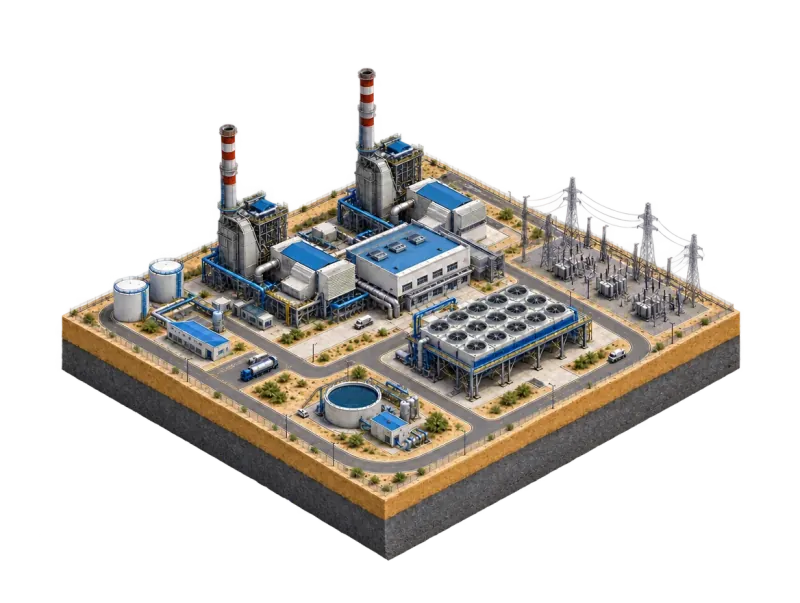
Central Combined-cycle power plant
Coast Steam power station
Negev Solar thermal tower
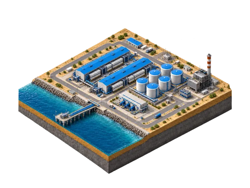
Coast Desalination plant
Haifa Bay Refinery & petrochemicals
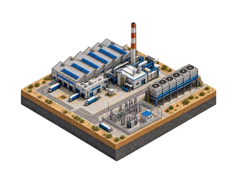
North Industrial cogeneration

What we do

One accountable supplier between the manufacturer and your plant.

Sourcing & import

We buy directly from the manufacturers we represent and handle shipping, customs and documentation into Israel.

Technical selection

We size and specify each part against your duty — pressure, temperature, materials and the existing installation.

Spares planning

We plan critical spares around your outage schedule, so the part is on site before the shutdown starts.

Local support

Installation guidance, commissioning support and after-sales service from a team based in Israel.

Product range

Product range

Flow control · final control element

Control Valves

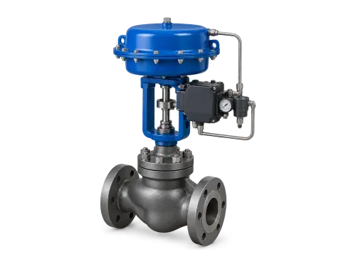
Globe control valve with a blue pneumatic diaphragm actuator and positioner
Types
Globe and angle bodies
Services
Steam, feedwater, process control
Standards
IEC 60534 series

A control valve regulates flow by varying the size of the flow passage on a signal from a controller — and through flow, it holds the pressure, temperature or level that depends on it. In loop terms it is the final control element.

How it works

Body and trim. In a globe valve, a plug on the stem moves against a stationary, replaceable seat ring inside a body divided by an internal baffle. In cage-guided trim, plug travel uncovers more of the cage’s ports, so flow rises with lift. Bodies are straight-through, angle (ports at 90°) or Y-pattern.

Actuator and positioner. A pneumatic, hydraulic or electric actuator moves the trim. The positioner feeds the actuator until stem position matches the set point — an inner loop that holds the valve where the controller asks.

Signal. 4–20 mA is the industrial standard; pneumatic loops use 3–15 psi (0.2–1.0 bar). Microprocessor-based digital positioners also communicate over HART, FOUNDATION Fieldbus or PROFIBUS.

Fail-safe. With a spring-return actuator the valve goes to a defined position on loss of air or signal — fail-closed or fail-open, as the duty requires.

What to specify

  • Fluid and flow range, with inlet and outlet pressure and temperature at installed conditions — the inputs for sizing to IEC 60534-2-1
  • Body pattern: straight-through globe or angle
  • Fail action on loss of air or signal
  • Actuator, positioner and signal: 4–20 mA, HART, FOUNDATION Fieldbus or PROFIBUS

Severe service · power generation

Critical Control Valves

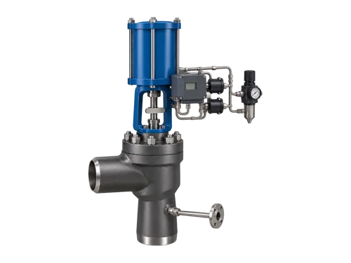
Angle-pattern turbine bypass valve with butt-weld ends, a spray-water connection and a blue pneumatic piston actuator
Services
Turbine bypass, steam conditioning, feedwater, pressure letdown
Duty
Start-up, shutdown and turbine trip; high pressure drop
Standards
IEC 60534 series · IEC 60534-8-3 and 8-4 (noise prediction)

Control valves for the most severe duties in a power plant: steam at boiler pressure and temperature, a large pressure drop, and a valve that has to open at once when the turbine trips.

Applications

  • Turbine bypass systems
  • HP/LP bypass
  • Steam conditioning
  • Feedwater control
  • Pressure letdown
  • Desuperheating
  • Severe service control

How it works

Turbine bypass. A boiler cannot be shut down instantly. When the turbine cannot take its steam — at start-up, shutdown, low load or a trip — the bypass routes the steam around the turbine instead of lifting the safety valves. At start-up it lets steam temperature be matched to the turbine metal before loading; on a trip it goes into full service immediately.

HP and LP stages. The HP bypass takes main steam around the HP turbine into the cold reheat line, so steam keeps flowing through the reheater and cools its tubes. The LP bypass takes hot reheat steam around the IP and LP turbines to the condenser.

Steam conditioning. Each stage reduces pressure and injects spray water to lower the temperature — feedwater-pump discharge on the HP side, condensate on the LP side — so neither the reheater nor the condenser is overheated.

Liquid letdown. Where water takes a large pressure drop, pressure at the vena contracta can fall below vapour pressure and bubbles form. If pressure recovers downstream they collapse — cavitation; if it does not, the water flashes.

Noise. A high pressure drop in steam or gas generates aerodynamic noise in the valve and the pipe expanders downstream. IEC 60534-8-3 gives the prediction method; IEC 60534-8-4 covers liquid flow, including cavitation.

What to specify

  • Sizing cases — cold, warm and hot start, normal operation and turbine trip — each with steam flow, pressure and temperature
  • Required outlet temperature, and the spray-water source, pressure and temperature
  • Opening time on a trip, and the fail position
  • Noise limit, predicted to IEC 60534-8-3 or 8-4
  • Line sizes, pressure class and end connections

Pump protection · minimum flow

Pump Protection Valves

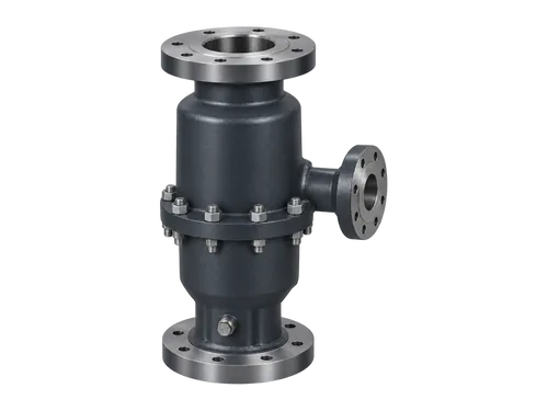
Automatic recirculation valve with flanged inlet, main outlet and a smaller bypass outlet
Types
Automatic recirculation (ARC) valves, minimum-flow control
Services
Boiler feed, high-energy water, process pumps
Reference standards
API 610 / ISO 13709 · ANSI/HI 9.6.3 (pump operating regions)

A centrifugal pump has a minimum continuous flow — the lowest flow it can run at permanently without damage. Plant demand often falls below it, at start-up and at low load. A pump protection valve holds the pump above that minimum by returning flow to the suction side whenever the process takes less.

Applications

  • Boiler feed pump protection
  • Minimum flow applications
  • Recirculation systems
  • High-energy water service
  • Process pump protection

How it works

Why a minimum. Against a closed or nearly closed outlet, the energy the impeller puts into the trapped liquid turns into heat — enough to flash it to vapour. Below the minimum continuous stable flow marked on the pump curve, hydraulic instability brings pressure pulsation, vibration and axial shuttling of the rotor. The thermal limit is usually the lower of the two.

Automatic recirculation valve. A self-operated three-way valve on the pump discharge. Forward flow lifts a guided, spring-loaded check element, which passes flow to the process and stops backflow through the pump. Its stroke works the bypass: as process demand falls toward the minimum, the bypass opens and returns the difference to the tank or suction line; above the minimum it is fully closed. No external power is needed.

Pressure letdown. The return line runs far below pump discharge pressure, so the bypass carries pressure-reducing internals that prevent flashing and cavitation in the return line and tank.

Alternatives. A fixed orifice in a continuous bypass is simpler but loses the minimum flow all the time, which considerably reduces pump efficiency — acceptable only for small, low-pressure pumps. Larger, high-pressure pumps use an automatic recirculation valve or an actuated control valve driven by a flow measurement.

What to specify

  • Pump curve, with the minimum continuous flow set by the pump manufacturer
  • Normal and maximum process flow
  • Pump discharge pressure, and the pressure at the bypass return point
  • Fluid and temperature
  • Line sizes and pressure class of the main and bypass connections

Valve automation

Actuators

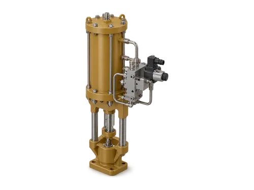
Hydraulic linear actuator with manifold block and servo valve
Types
Pneumatic, hydraulic, electric
Duty
On/off and modulating
Mounting
EN ISO 5211 (part-turn) · EN ISO 5210 (multi-turn)

An actuator is the mechanism that opens and closes a valve. Power-operated, it lets a valve be positioned remotely and moves large valves quickly — including valves too big, too remote or too hazardous to work by hand.

How it works

Pneumatic. Air pressure acts on a diaphragm or a piston; pistons run at higher pressure and give more thrust than diaphragms. Double-acting units drive both ways by admitting air to either side; spring-return units go to a set position when air is lost.

Hydraulic. Liquid is nearly incompressible, so hydraulic actuators exert large forces and respond quickly, with little inertia. In electrohydraulic units an electric motor charges a hydraulic accumulator that delivers the stroke.

Electric. Typically a three-phase asynchronous motor driving through a worm gear. Limit switches mark the end positions, torque switching measures the torque in the valve, and a transmitter reports position as a continuous 4–20 mA signal.

Motion. Linear actuators stroke rising-stem valves such as globe and gate valves; part-turn actuators rotate quarter-turn valves such as ball and butterfly; multi-turn actuators drive valves that need several turns of the stem.

Fail-safe. Spring and hydraulic designs store energy to drive the valve to its safe position when power or signal is lost.

What to specify

  • Valve type, and so the motion: linear, part-turn or multi-turn
  • Thrust or torque required, and stroking time
  • On/off or modulating duty, and the fail position
  • Power available on site: instrument air, hydraulic supply or electrical
  • Mounting interface: EN ISO 5211 (part-turn) or EN ISO 5210 (multi-turn)

Shut-off

Isolation Valves

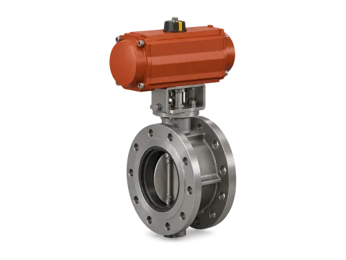
Flanged triple-offset butterfly valve with a quarter-turn actuator
Types
Triple-offset butterfly, gate, ball
Duty
Tight shut-off at high pressure and temperature
Standards
API 609 (butterfly valves)

Isolation valves stop flow rather than regulate it, so a line or a machine can be taken out of service safely — for a trip or for maintenance. We supply the three main families: butterfly, gate and ball.

How it works

Triple-offset butterfly. A quarter-turn disc on a shaft. The shaft is offset from the seat centreline and from the bore centreline, and the seat’s contact axis is offset as well — together they virtually eliminate sliding contact between disc and seat. That allows a metal seat, machined to give bubble-tight shut-off. Butterfly valves are also lighter than other designs, so they need less pipe support.

Gate. Opens by lifting a gate — usually wedge-shaped, to load the sealing faces — clear of the flow path. Fully open there is no obstruction and very little flow resistance, but flow does not track stem travel, so gate valves isolate rather than throttle. A rising stem shows position at a glance; a non-rising stem saves headroom.

Ball. A bored ball turns 90° between open and closed. A floating ball shifts slightly downstream under line pressure; a trunnion-mounted ball is anchored top and bottom, for larger sizes and higher pressures. Full-port bodies match the pipe bore for minimal friction loss.

What to specify

  • Line size, pressure class and design temperature
  • Required shut-off tightness
  • Butterfly body style: double-flanged, lug or wafer (API 609)
  • Ball valves: full or reduced port
  • Operation: manual, gear or actuated for remote or emergency isolation

Steam conditioning

Desuperheaters

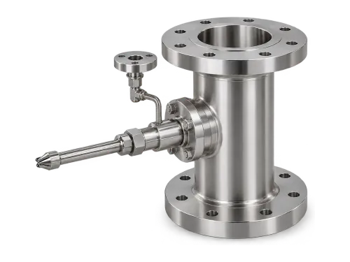
Stainless-steel desuperheater spool with a spray-water nozzle assembly
Type
Spray-water, direct contact
Services
Process and bypass steam lines
Approach
About 8–10 °C above saturation (spray types)

A desuperheater cools superheated steam back to, or close to, saturation. Superheat suits a turbine, keeping water droplets off the blades; for heating and process duty it is a handicap, because the heat-transfer coefficient of superheated steam is variable, low and hard to quantify. At saturation the coefficient rises sharply and steam condenses at a constant temperature, so heat exchangers can be sized and controlled accurately — and made smaller.

How it works

Spray injection. Cooling water enters the steam through one or more nozzles. Each droplet absorbs heat as it evaporates and becomes steam itself, taking superheat out of the flow.

Atomisation. The finer the droplets, the shorter the distance they need to evaporate. Droplets that fall out of suspension cut efficiency and cause corrosion, so the downstream pipe run is part of the design; vertical up-flow keeps water in suspension and extends turndown.

Control. A valve sets the cooling-water flow from the steam temperature measured downstream of the desuperheater, with inlet steam pressure held constant.

Turndown and approach. Single-point radial and axial spray designs typically reach 3:1 turndown at most and cool to about 10 °C above saturation. Multi-nozzle axial designs reach 8:1 (fixed area), 9:1 (spring-assisted) or 12:1 (variable area), to about 8 °C above saturation.

What to specify

  • Steam flow range, minimum to maximum — this sets the turndown, and so the type
  • Inlet steam pressure and temperature, and the outlet temperature required
  • Cooling-water pressure and temperature
  • Line size, orientation and the straight run available downstream

Combustion safety · burner management

Combustion & Flame Monitoring

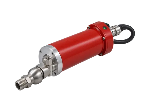
Industrial flame scanner with a swivel mount, purge-air tee and armoured cable
Detection
UV, IR and UV/IR flame scanners · flame rods
Ignition
Gas and oil igniters, high-energy spark igniters, pilot burners
Standards
NFPA 85 (boilers) · EN 298 (automatic burner control systems)

A burner may run only while its flame is proven. The flame detector gives that proof to the burner management system, which shuts off the fuel when the flame is lost — before unburned fuel can collect in the furnace.

Applications

  • Flame detection
  • Igniters
  • Pilot burners
  • Combustion safety
  • Furnace and boiler monitoring
  • Burner management support

How it works

UV scanners. Respond to ultraviolet below 300 nm, emitted at ignition, within 3–4 ms. Arc welding can trigger them, and an oily film on the viewing window can blind them.

IR scanners. Respond to infrared from the hot combustion gases, and use the flame’s flicker, at 1–20 Hz, to tell it from steady radiation off hot surfaces. UV/IR scanners compare both bands to cut false signals.

Flame rods. An electrode in the flame. Flame rectification lets current pass more easily in one direction, which proves the flame. A dirty rod or a flame lifting off the burner breaks the signal.

Igniters and pilots. NFPA 85 classes igniters by their capacity against the main burner’s full-load input. Class 1, generally above 10 %, can light the main burner and support it under any condition. Class 2, generally 4–10 %, lights it under prescribed conditions and supports it at low load. Class 3, generally below 4 %, is for light-off only; a Class 3 special is a high-energy electric igniter that lights the main burner directly. Igniter flame must be proven before main fuel is admitted.

What to specify

  • Fuels, burner type and firing rate
  • Single- or multiple-burner furnace, and the sighting position for each scanner
  • Igniter class, and the igniter or pilot fuel
  • Interface to the burner management system: flame relay outputs, signals and supply voltage
  • Ambient temperature at the scanner, and the purge or cooling air available

Condition monitoring

Digital & IIoT

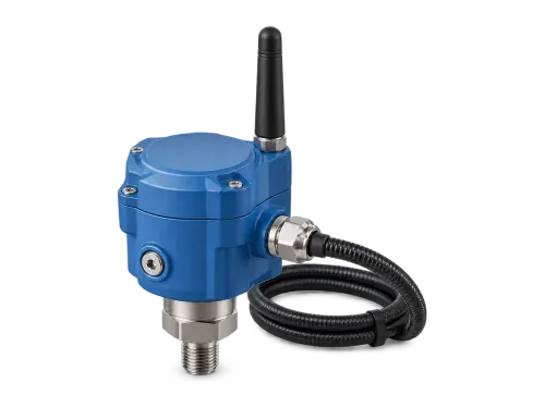
Wireless vibration and temperature sensor with armored cable
Measures
Vibration and temperature
Purpose
Condition monitoring, predictive maintenance
Reference standards
ISO 20816 (machine vibration) · IEC 62591 (WirelessHART)

Sensors that track the condition of plant — vibration and temperature — so a developing fault shows up early, often weeks or even months before failure. Maintenance is then planned on measured condition and done only when warranted, rather than by the calendar.

How it works

Vibration. Accelerometers on the bearing housing measure casing vibration; eddy-current proximity probes measure shaft displacement directly. An FFT turns the time signal into a spectrum, where faults appear at characteristic frequencies: high vibration at running speed most often means residual imbalance, while a degrading rolling-element bearing shows at specific frequencies that grow as it wears.

Temperature. Rising temperature is a second sign of a failing component.

Wireless. Wireless sensor networks cut the cost of wiring sensors into existing plant. WirelessHART (IEC 62591), built on the HART protocol, is a self-organising mesh: each device also routes for its neighbours, giving redundant paths, on 2.4 GHz IEEE 802.15.4 radios.

Data. Readings are processed at the edge, in the cloud or both, and can be integrated with the computerised maintenance management system (CMMS).

What to specify

  • Machine type, speed and bearing type
  • Measurement: casing vibration (accelerometer) or shaft displacement (proximity probe)
  • Evaluation limits: ISO 20816-3 covers industrial machines above 15 kW running at 120–30 000 r/min
  • Network and integration: wireless or wired, into the control system or CMMS

Field services

We don’t stop at supplying the part. ARAVA puts technicians, supervisors and specialist crews into the plant for turbine, generator and valve work on critical power plant equipment — through planned outages and shutdowns.

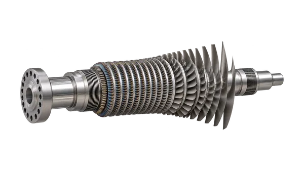
Steam turbine rotor with bladed stages, bearing journals and coupling flange

Turbines & generators

Turbine & generator outage support

Crews and supervision for steam turbine and generator outages, from planning through commissioning.

  • Mechanical technicians
  • Supervisors
  • Specialised turbine labour
  • Generator maintenance crews
  • Outage planning support
  • Commissioning assistance
Plan outage support
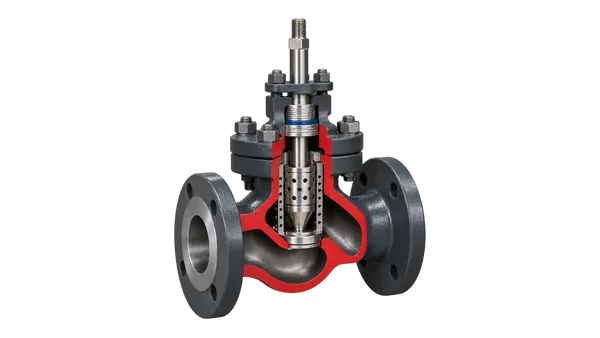
Cutaway globe control valve showing the cage, plug, seat ring and stem packing

Valves

Valve services

Inspection, diagnostics and repair on site, and the audits and programmes that keep critical valves reliable between outages.

  • Valve diagnostics
  • On-site inspection
  • Maintenance & repair
  • Overhaul supervision
  • Shutdown support
  • Spare parts management
  • Valve audits
  • Reliability programmes
Ask about valve services

Maintenance & upgrades

Industrial Flow Control, Combustion& Maintenance Services

Supporting Power Generation, Petrochemical and Industrial Facilities Across Israel

Arava Technologies provides engineered solutions for critical control valves, pump protection valves, flame detection systems, ignition equipment and lifecycle field services for power generation and industrial customers throughout Israel.

Maintenance & overhauls

Planned and emergency work on turbines, valves and auxiliaries, timed to your outage window.

Upgrades & retrofits

Obsolete parts replaced with current equivalents, engineered to fit the existing installation.

Our engineers, our responsibility

We bring the engineers, manage them on site and sign off the work through handover.

Contact

Tell us what you need.

Send a part number, a datasheet, or a plain description of the problem. An engineer will get back to you.

Phone
+972-3634-1644
Email
info@aratech.co.il
Office
Shamira Imber Gadish 9, Kiryat Ono, Israel

Give a part or subject, a message, or both.

Goes straight to our engineering inbox. You don’t have to give us your details, but we need a name and email to reply, and we use them only to answer this request. Privacy notice